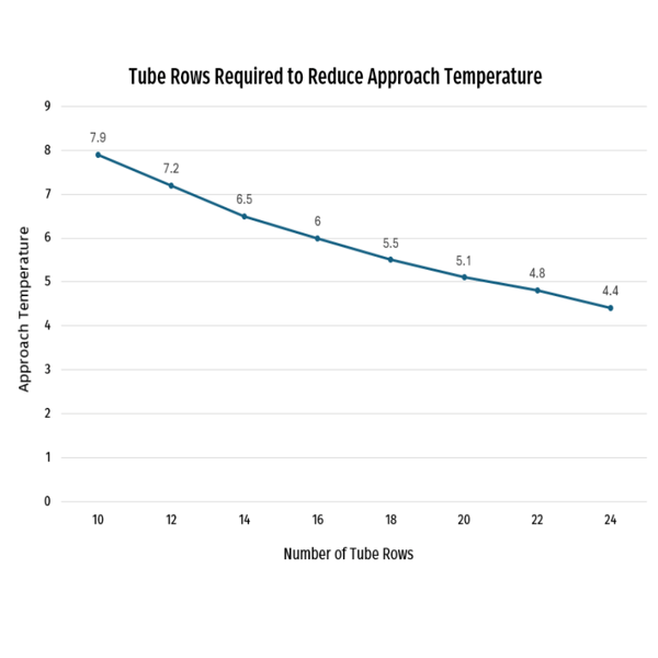
5mm Direct-to-Chip Fluid Coil
TUBES
Built using 5mm tubes to maximize heat rejection with minimal footprint. This coil featured 12 tube rows.
FINS
To maximize airside heat transfer, the coil was built using corrugated aluminum fins with a density of 15 fins per inch.
PERFORMANCE REQUIREMENT
This application required a pressure drop of less than 1%, and was designed to meet a specific heat rejection target.
MANUFACTURING CONSIDERATIONS
Back gas was specified during the brazing process, & coils were tested using 100 PSI helium to ensure a leak rate of < 3.3 x 10(-5) atm. cm/sec.
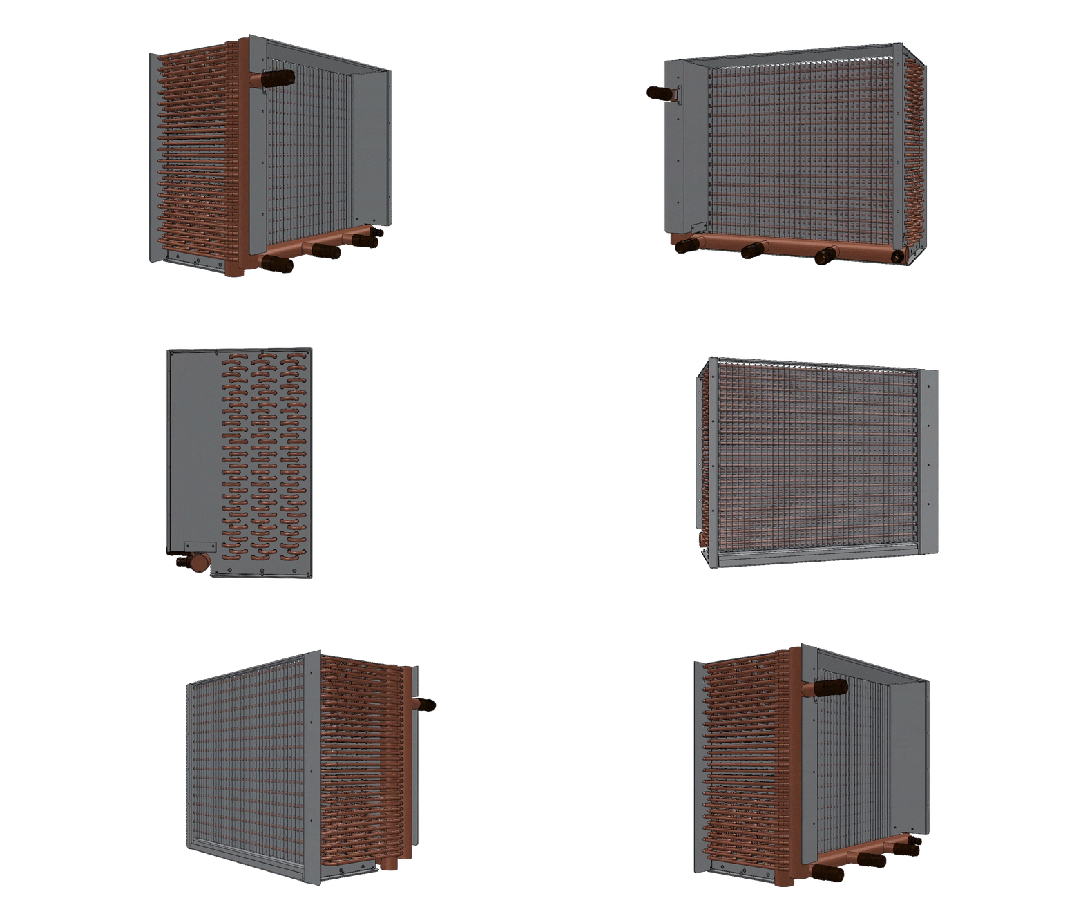
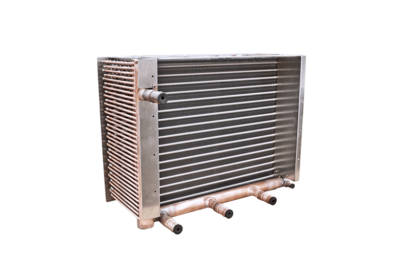
Rear Door Heat Exchanger for Supercomputer Application
TUBES
This fluid coil featured a 2-row design to maximize heat rejection within the existing footprint of the server rack's rear door. It was built using 3/8" OD copper tubes with a wall thickness of .014".
FINS
Aluminum raised lance fins with a thickness of .0055" were used to maximize airside heat transfer. Fins were spaced at 12 fins per inch to increase heat transfer surface area.
PERFORMANCE REQUIREMENT
This coil was engineered to reject roughly 10F degrees of heat from the server rack into the environment, and was designed to accommodate increased load conditions when needed.
MANUFACTURING CONSIDERATIONS
Spring turbulators were inserted into the coils tubes to maximize fluid turbulence and improve heat transfer. Headers were designed to fit with existing connections in the server cabinet.
.gif?width=800&name=VA1022666%20(1).gif)
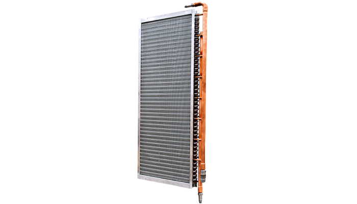
Fluid Coil for High-Performance Computing Application
TUBES
This coil featured an 8-row design to maximize tube-side heat transfer. Copper tubes with an OD of 3/8" and a wall thickness of 0.16" were used.
FINS
Standard aluminum fins were used for this coil. The fins featured no surface enhancements, but were spaced at 17 fins per inch to maximize heat transfer surface.
PERFORMANCE REQUIREMENT
These coils were designed to reject up to 36F degrees of heat away from a high-density server cabinet.
MANUFACTURING CONSIDERATIONS
The coil was designed for a preexisting envelope with very tight spatial tolerances. Return bends and hairpins were required to be inside of the coil's end plates to allow it to fit within the unit.
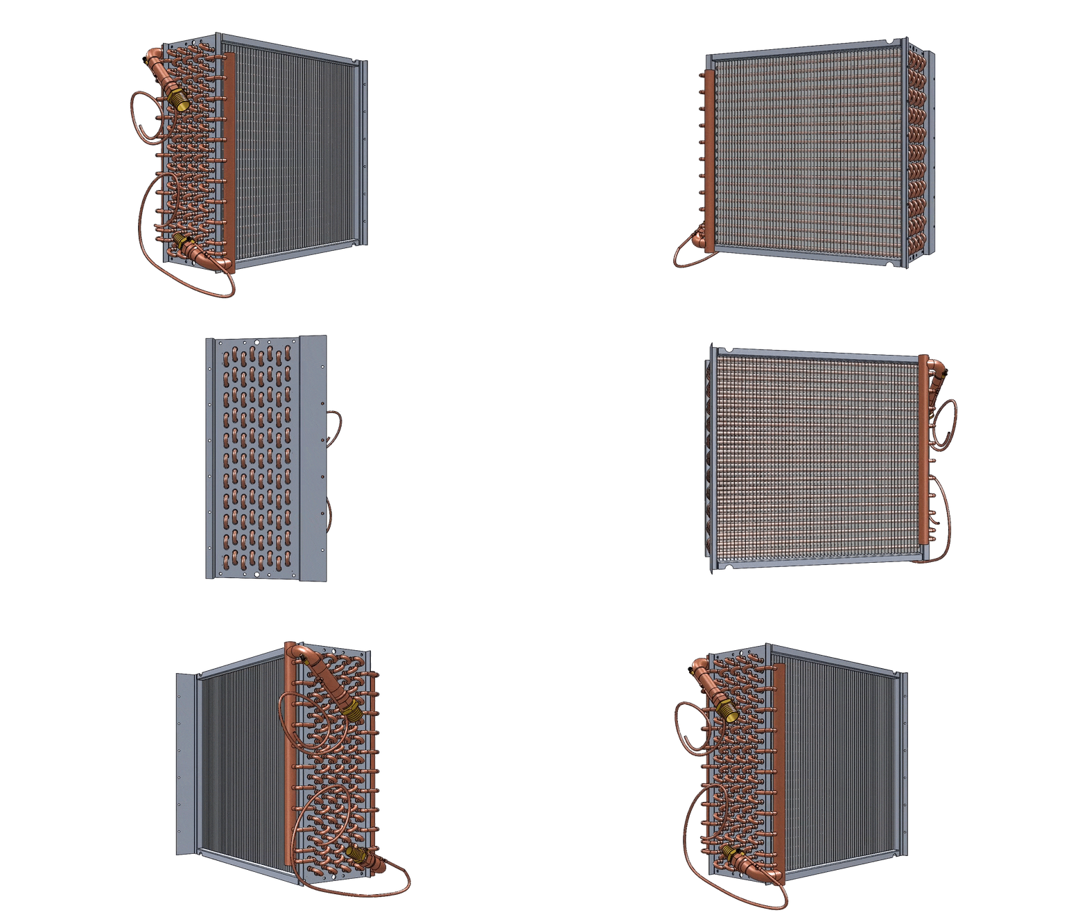
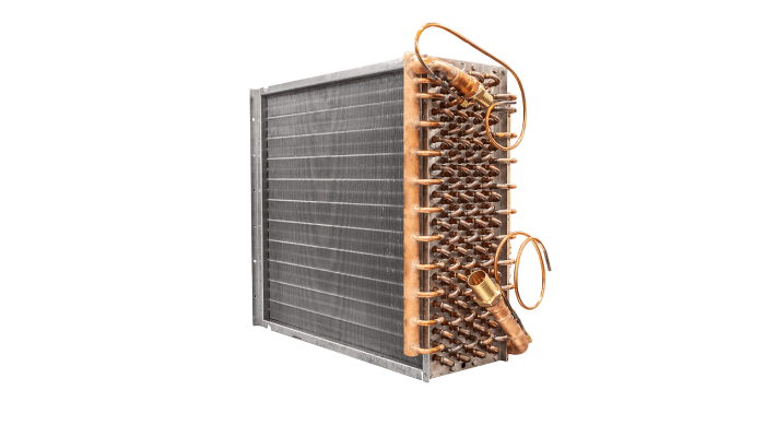
8-Row Evaporator Coil
TUBES
This coil featured an 8-row design to maximize internal heat transfer within a predetermined envelope. Copper tubes with an OD of 3/8" and a wall thickness of 0.032".
FINS
This 9" x 24" coil was built using standard aluminum fins with a corrugated pattern and a thickness of 0.0075". Fins were spaced at 12 fins per inch.
PERFORMANCE REQUIREMENT
This coil was used for a post-cooling application in a data center, and was designed for a 21F delta T. The coil was circuited in a thermal counter flow arrangement and has a capacity of 12,215 Btu/hr.
MANUFACTURING CONSIDERATIONS
This design included a 1/4" x 36" equalizer line that was attached to the suction header.
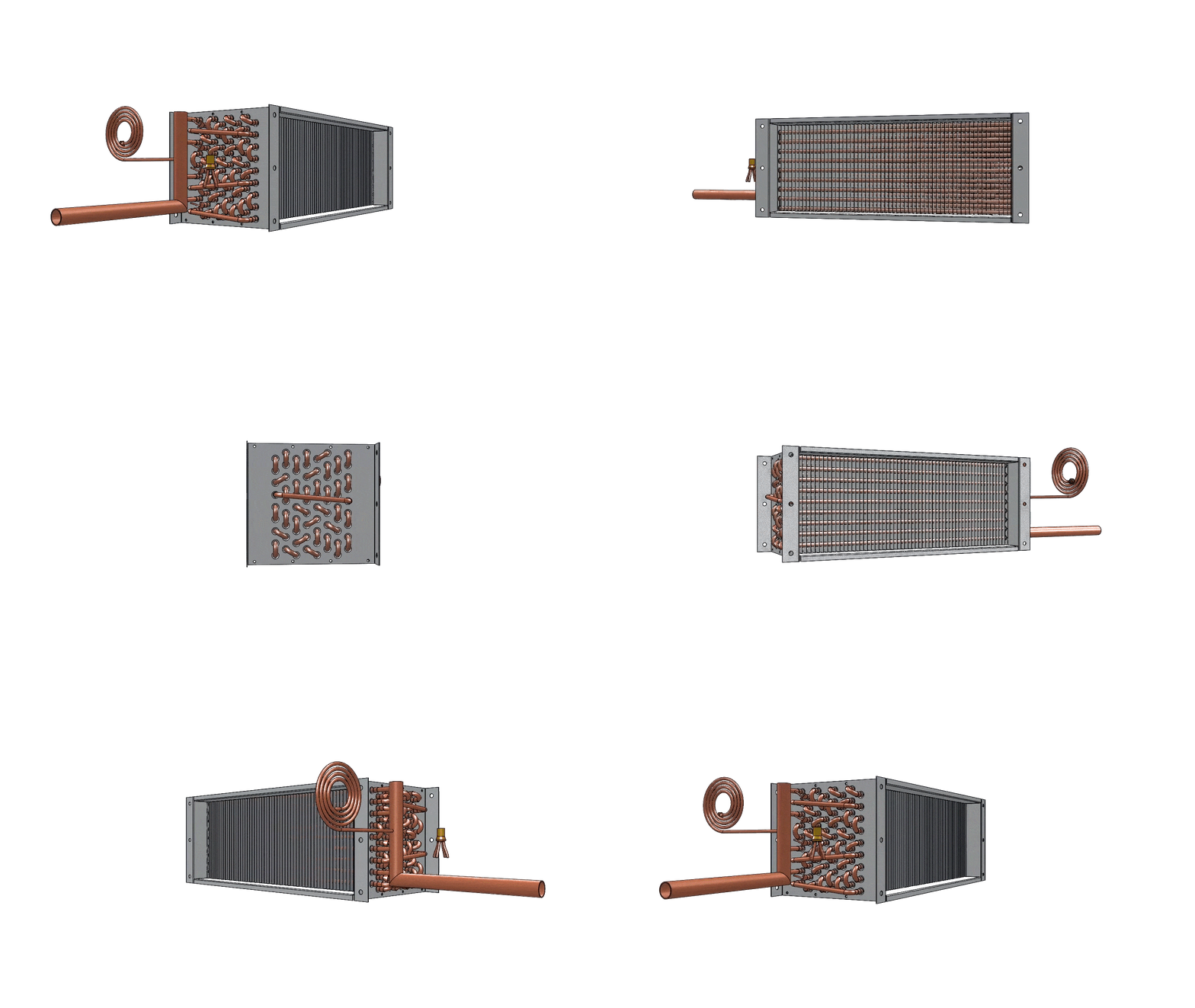
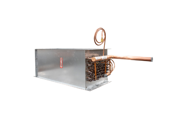
Coils Designed for Quality, Performance, and Customizability
.png?width=591&height=591&name=iStock-1454227730%20(1).png)
100+
0-90

10,000+
Designed for Compatible Performance
When space for coils is limited and underperformance isn’t an option, our engineers get to work. We’ll help you find the air friction sweet spot and reach the upper limit of heat transfer possibility while ensuring our coils are designed for compatibility with existing equipment’s configuration and orientation.
%20(1).webp?width=442&height=500&name=image%2013%20(1)%20(1).webp)
Our Process
Initial Design & Prototyping
We’ll learn your performance requirements, spatial constraints, and other application-specific details to develop an initial design and prototype.
Performance Testing & Design Optimization
If desired, we can performance test your coils in our in-house wind tunnel to validate performance ratings based on real-life data, not extrapolations.
Design Finalization & Drafting
Once your design is approved, we’ll generate technical drawings and begin the process of releasing the coils for production.
Production & Delivery
Your approved final design is released to our manufacturing facility for production. We’ll work with you to coordinate production & delivery schedules in accordance with your needs.
FAQ
Absolutely. We regularly build data center and electronics cooling coils with auxiliary componentry. Examples include manifolds, special connections, and casings to make sure your coils are the right tool for the job they’ll be used for. If it’s something we think we can do well, and the request pairs well with our manufacturing processes, we’re happy to provide those kind of additions. And, if it’s something we’re not familiar with, we’re happy to see if it’s something we can add into our process.
Absolutely. We regularly provide our data center and electronics cooling customers with both services. Our wind tunnel test laboratory can be at the customer’s disposal so they can be confident in their performance capabilities thanks to real-world, validated testing data, not extrapolations or formulas.
We can. Ample design capacity is a critical ingredient in our ability to support complex, high-volume data center and electronics cooling projects. So, our design engineering department is one of our largest, featuring more than 30 mechanical engineering professionals who generate hundreds of designs per month.
Fluid coils are the most common, but we also make condensers and evaporators for a variety of data center and electronics cooling applications. Our selection software can rate coils for fluids (water, propylene, and ethylene glycol) as well as all the latest synthetic refrigerants.


