Coil circuiting and its relationship with the application’s airflow are critical considerations of coil design, as proper circuiting can help increase the heat transfer coefficient of the heat exchanger.
On the other hand, improper circuiting can lessen a coil’s effectiveness and even cause damage, like tube erosion resulting from insufficient calculations for fluid velocity, for example. So, it’s important to understand the forces at play before deciding on a circuiting layout.
In this post, we’ll look at some important considerations when deciding on how you want your coil to be circuited, including:
- Types of fluid paths relative to airflow direction
- Parallel flow
- Counter flow
- Cross flow
- Number of circuits
- Important considerations
Circuiting considerations differ between single-phase and two-phase coils. This post will focus on single phase coils, specifically fluid coils. But, with either case, the primary issue caused by improper circuiting is diminished heat transfer performance.
Looking for help optimizing your coil circuiting? Give SRC a call or submit a request for quote form to tell us more about your application.
As the name implies, the working fluid in single-phase coils remains in a single state during the entirety of its passage through the coil’s tubes (gaseous or liquid). Examples of single-phase coils include:
- Water coils (chilled water, hot water, glycol)
- Brine coils
- Oil coils (thermal, lube, hydraulic)
- Air-to-air or gas-to-gas coils
- Desuperheaters, sub-coolers, & intercoolers
Types of Fluid Paths Relative to Airflow Direction
Typically, decisions on circuiting configurations are made with the intention of balancing heat transfer with pressure drop & fluid velocity. Optimizing a coil’s circuitry improves performance, allowing for a smaller, less costly coil. The standard circuiting patterns that we use at SRC are explained below.
Thermal Counter Flow
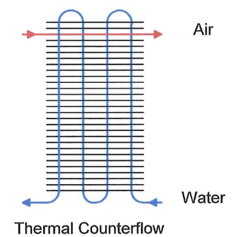
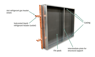
Thermal counter flow describes a configuration in which the air flows in a direction counter to that of the fluid with a coil’s tubes. Typically, counter flow is viewed as the most effective circuiting configuration for single-phase fluid applications, allowing for the greatest ΔT throughout the coil.
Cross Flow
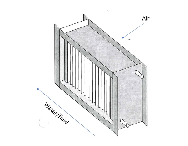
A cross flow circuiting pattern effectively splits the difference between thermal counter flow and parallel flow, which we cover next. In such a pattern, the coil’s fluids flow 90 degrees to one another. In cross flow circuiting, the ΔT will average out, typically exceeding that of parallel flow.
Thermal Parallel Flow
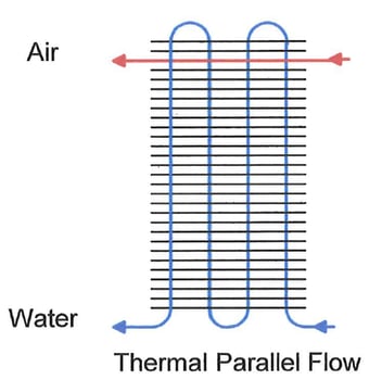
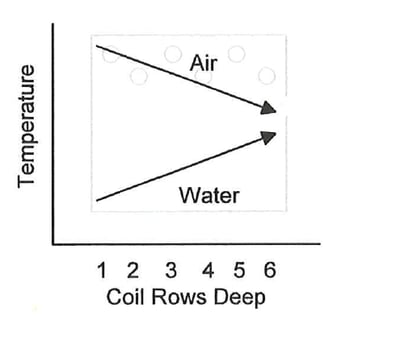
With circuiting designed for thermal parallel flow, the fluid within a coil’s tubes and the air that’s forced across a coil’s face flow parallel to one other. With parallel circuiting, the ΔT between the fluids is initially very high, but decreases rapidly as the fluids’ temperatures approach one another.
While not the most efficient option, parallel flow is commonly used when a user wants to keep the tube-side fluid above a certain temperature. One such example is internal economizers, which preheat feedwater as it enters a boiler, which reduces thermal shock and improves efficiency.
Number of Circuits
Determining the proper number of circuits is a critical step for designing an effective heat exchanger. Optimizing the number of circuits in a coil allows the engineer to control the speed with which the working fluid flows through the coil as well as the resulting pressure drop, both of which have a direct impact on the heat transfer of the equipment.
The number of circuits describes the number of tubes that are fed to the supply header. The explanations below refer to a fluid coil with a thermal counter flow configuration as examples.
Single serpentine (also called full circuit): In this configuration, all tubes in the first vertical row feed the supply header.

Double serpentine: In this arrangement, the first and second vertical row would be fed from the supply header.

Half serpentine: In a half serpentine circuiting configuration, every other tube in the first vertical row is fed by the supply header.

Depending on the number of tube rows in a coil, other circuiting patterns are also possible, such as three-quarter serpentine, one-quarter serpentine, 1 1/2 circuiting, etc.
Important Considerations
There are three primary elements to consider before deciding on the configuration of your coil’s circuiting:
- Connection location: Are the coil’s supply and return connections located on the same end or opposite one another? This will impact installation orientation and, in the case of same-side connection steam distributing coils, may preclude certain types of heat exchangers from being used (using a return bend type of coil in such situations is not recommended).
- Installation orientation (vertical or horizontal): It’s important to note that circuiting can change depending on the orientation of the coil when installed. Be sure to discuss how you plan to install the coil when working with the engineer that is designing your coil or system.
- Number of passes: A pass describes each time a fluid goes through the length of a tube. Multiple passes within the same tube can increase heat transfer, but it comes with an increased pressure drop.
If you're interested in engineering support when designing coil circuits, or are looking for a coil vendor to help optimize your coil designs to maximize performance, give Super Radiator Coils a call or submit a request for quote form. We'd love the opportunity to help you get the most out of your heat transfer components.
Don’t get left out in the cold when it comes to heat transfer information. To stay up to date on a variety of topics on the subject, subscribe to The Super Blog, our technical blog, Doctor's Orders, and follow us on LinkedIn, Twitter, and YouTube.


