As anybody who has ever designed heat transfer equipment will tell you, it all comes down to tradeoffs. The specifics of the application and the priorities of the equipment’s end user will always have the greatest impact on a heat exchanger’s eventual design. For some applications, minimizing a coil’s total cost is the top priority. In such situations, our engineers will try to design a heat exchanger that’s as small as possible, using the least amount of raw materials and labor needed to meet the thermal requirement. On the other hand, for a heavy industrial application where service life and durability are the considerations of record, our approach to heat exchanger design would be entirely different.
One of the most common – and often misunderstood – tradeoffs we navigate has to do with an application’s approach temperature, which is essentially the difference between the hot and cold streams in the heat exchanger. With a chilled water coil, for example, the approach temperature would be the difference between the outlet temperature of the air being cooled and the inlet temperature of the water absorbing the heat.
In theory, an optimally designed coil would have an approach temperature of 0F – which would represent an efficiency of 100% – which is impossible to achieve in practice.
Not only is it impossible to achieve a zero-degree approach temperature, but pursuing the smallest delta possible, while presenting an opportunity for potential incremental improvement, can result in diminishing returns beyond a certain point.
It’s a matter of “is it worth it?” For example, adding heat transfer surface – such as extra tube rows or fins per inch – is a reasonable method to reduce approach temperature, but doing so comes with its own set of drawbacks, such as:
- Air friction: adding tube rows or increasing fin density can help toward narrowing a coil’s approach temperature, but doing so introduces added air friction, increasing power consumption and potentially offsetting any efficiency gained by the reduction. Denser fin packs and extra tube rows can also increase the potential for airside fouling issues as well as adding cost.
- Higher flow rates: pressure drop on the fluid side of the coil increases with each tube row added to the design, which requires changes to pump selection. Higher tube-side pressure drop requires more powerful – often larger – pumps, adding cost and creating the potential for issues if fitting that larger equipment in an existing profile. Higher fluid-side pressure drop also reduces fluid velocity, contributing to reduced performance and efficiency.
- Material cost: pretty straightforward here – more metal = more expensive.
- Time: any time a revision is made to a coil design – be that changes to tube configuration, adjustments to fin geometry/density, or something else – it takes up engineering, drafting, and other resources, which increases costs. More importantly, revisions of this nature generally prolong the coil design/build process, resulting in a longer time between initial design and finished product.
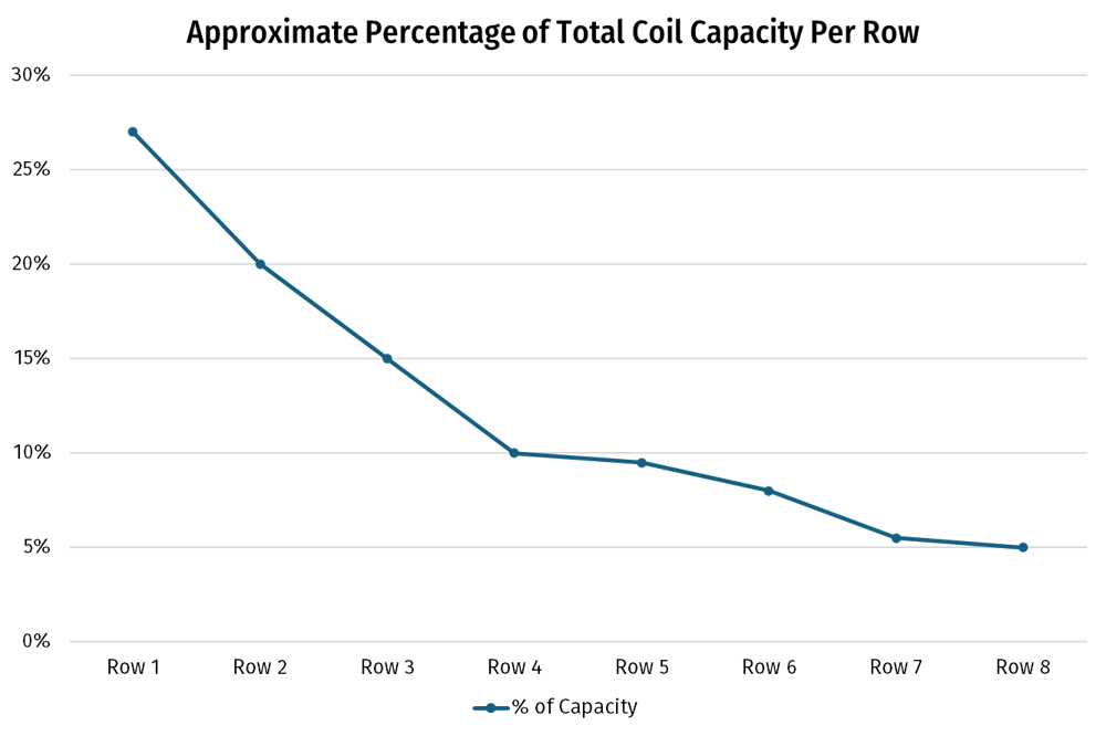
While very close approach temperatures can be achieved, it might be a more useful exercise to ask the question of whether doing so is truly necessary for the application’s viability. The graphs below illustrate that after a certain point, the pursuit of the closest approach temperature possible becomes significantly more difficult and complicated. The first graph shows the heat transfer capacity of an 8-row coil by tube row. More than half of the coil's capacity is realized within the first eight tubes, with each subsequent tube - especially past the fourth tube row - resulting in significantly lower heat transfer per tube row.
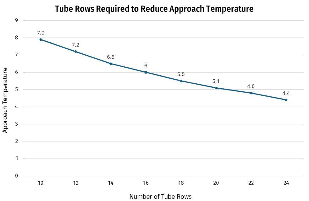
Similarly, the following graph illustrates that diminishing return dynamic in a real-world coil application. In this exercise, achieving a 6.3°F reduction in approach temperature required a 140% increase in the number of tube rows. For the overwhelming majority of scenarios, this design change would be unfeasible, as the additional tube rows in this example would result in more than a 50% cost increase.
Furthermore, these graphs show the importance of circuiting configuration in designing the most effective heat exchanger possible. Proper flow type (counter, parallel, cross, etc.), number of circuits, and circuiting configuration can be far better areas to focus on if minimizing the application’s approach temperature is the goal, rather than adding tube rows or other measures. Check out our article on fluid coil circuiting best practices for some more details on how to apply those principles.
Don’t get left out in the cold when it comes to heat transfer information and news. To stay up to date on a variety of topics on the subject, subscribe to The Super Blog, Super Radiator's News Feed, our technical blog, Doctor's Orders, and follow us on LinkedIn, Twitter, and YouTube.